This room-sized layout features most everything one needs in a home layout.
After spending many months studying track plans and drawing a few of my own I finally settled upon one that I felt provided all the features I wanted in my 11 x 12 foot room. I wanted to make sure things would work before committing track to plywood. I liked the features of an original plan by Leonard Blumenschine (first published in Nov ‘79 Model Railroader). His plan measured 6 x 12 feet and was free standing in the room, allowing one to walk around all sides of the layout. If I could shorten his plan by a foot, and build against 3 walls, it would fit my space. To help my understanding of how things would fit, I made a 1/12 size (1 inch equals 1 foot) scale paper model of my model railroad before I built it. I really learned a lot. This project took only about two days of concentrated work.
This was done by drawing the track plan, assisted by radius templates, onto card stock paper (blank IBM cards) then cutting it with scissors and gluing it all to a piece of wood board the same size as the finished table, 11 inches long. Upper level and inclining tracks were supported with accordion folded slivers of card and glue. That way I could better visualize the required grades and include some landscape scenery. This gave a good idea of future accessibility of restricted places. On this mock-up I used bits of Styrofoam cut with a razor blade to represent cars and buildings. These were painted realistic colors to assist the effect.
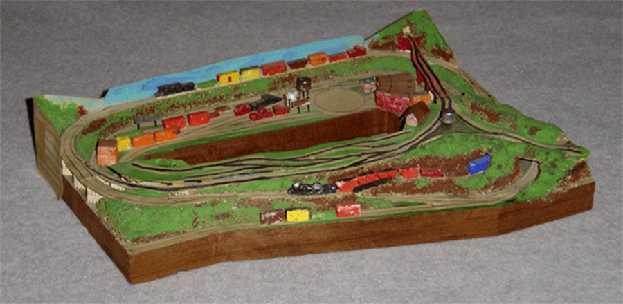
One can learn a lot by building a scale sized mock-up
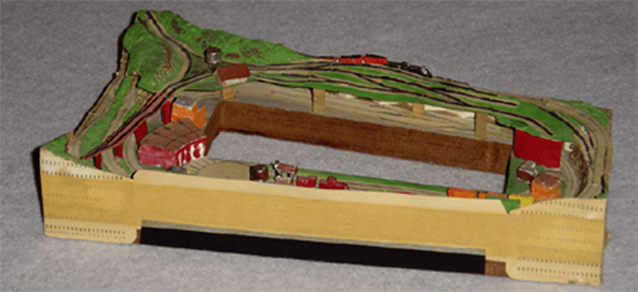
During this mock-up building venture I discovered that the space below the upper town of Hillton had enough room for a hidden double-ended train staging yard. Here a minimum vertical clearance of 8 inches with 3 inch track spacing will allow a hand to tend a derailment. This yard, not included on the original plan, is accessed from within the operation pit via an extended yard drill track. After I got the railroad into operation this staging yard has proven to be quite a valuable addition. I had a little more room for the upper town, so I enlarged it as much as is within arm’s reach. The mockup also showed that I could make the incline grade from Wall Bridge to Hillton Junction gentler.
After the layout construction was started it became apparent that by extending the interchange track, now on the front side of the table, one could add two additional train length tracks for hidden train storage below Hillton Junction if some method for derailment access was maintained. Concealing these tracks proved to be an exciting adventure years later.
The layout runs from Yardley engine terminal and classification yard or Holden Staging, past interchanges for two other railroads, the towns of Middleburg and Hillton Junction and then to the major industrial complex of Hillton with over a dozen rail-served industries.
The finished railroad has a few deviations from this mock up, which is now over 30 years old, and that fact stands as testament to the good idea it was to first build a mock up when space is tight. Such is how the HO scale Yardley and Hillton Railroad started.
Describing Features of the Yardley and Hillton:
I liked a track plan found in Kalmbachs 58 plans book by Leonard Blumenschine called the Weebeck and Sunmount originally published in the Nov. ‘79 Model Railroader. The layout I built was enhanced from the original plan by adding hidden train staging, a wonderfully valuable feature that I cannot speak too highly of. This layout features a single-track – two lap, separated grade crossing mainline serving 3 towns with passing sidings and industries plus a short branch to a busy town with a turn-around ‘Y’ track. The layout has a classification yard, roundhouse, turntable and hidden train storage. I wanted a layout that would fit my available space and offer good operation with an option for one or two operators. But I had a bit of a space deficiency so I tried making a scale model first to make sure things would fit properly. One can learn a lot by making a mockup of the layout before construction begins. This is even more important where spaces are tight.
Build a scale model first.
I made a 1-inch to the actual foot scale model of this layout by using the track plan drawn onto card stock paper and cut out with scissors before I built the real thing. I fashioned elevated tracks from accordion folded slivers of card and cars and locos cut with a razor blade from bits of Styrofoam. I was interested in proving the feasibility of some physical changes required by my cramped space that was one foot shorter with no room to walk around the outside of the layout. It was during this venture that I learned where my changes would not fit properly, such as the width at the lower end of Hillton. This mockup effort showed that I could include a hidden double-ended train staging yard below Hillton, a feature not shown on the original plan.
The layout is built against 3 basement walls. I operate it from either inside or outside the center hole with tethered throttles. (Yes, I have to duck under) I altered the plan somewhat to put the interchange track on the opposite side for better accessibility in my room. I added some features not on the original plan such as a modified version of the switching puzzle at Equinox – from the plan “Sagatuckett River RR” by Robert Silas published in Mar ‘72 Model Railroader, (even though my plan has more generous track lengths making the task easier). I think switching puzzles work better in hand than on paper. With it I can duplicate all the destinations and switching moves provided in the puzzle just by blocking access to one track with a couple blue flags. Perhaps there is some maintenance work being done to a turnout, which denies access to that route, and gives rise to the complexities of this fine switching problem. This can provide a real challenge to switching Hillton’s Outer industries. Give yourself about 20 minutes!
Another method of challenging your switching skills without using the outer pass is to have a string of cars destined to Hillton Inner industries on the inner pass at Hillton as though they had arrived from the Wherezatgo tunnel. You must do the required switching to spot those cars and return the out bounds without using the outer pass or the ‘Y’ track. You will appreciate the overlapping runaround tracks. Hillton has many more industries than Equinox. They are really crowded too close together to allow for believable scenery, but as I always say, with selective compression comes manageable congestion. The town offers a couple of train length runaround tracks and lots of industrial sites for switching traffic. My railroad is deliberately built heavy on industrial freight operation and light on scenery. It is able to accommodate 2 operators in less than 100 square feet of floor space. It has capacity for about 100 cars & 6 locomotives.
Changes can be for the good:
The biggest change to the track plan is the addition of a hidden double-ended train storage yard that I call Holden, directly below Hillton for a train staging option to the operation. This is an operational aid that I cannot speak too highly of. Hillton is raised about 8 inches above the table to allow hands on access to tend to the occasional derailment in the stage. Track spacing of at least 3 inches also helps here.
I located the fiddle interchange track right out front where it is easy for a visitor to mount his train if he brought one. During construction I realized that by putting a turnout at the far end of this interchange track I could make 2 additional tracks for hidden train storage. I envision these interchange tracks as Eastbound and Westbound off road traffic. They extend all the way back to the far wall directly below Hillton Junction and have a storage capacity of about 12 cars each. A couple other options would be to use these 2 tracks as Loads-in / Empties-out hopper industry or to store a complete passenger train.
I scratch built a small roundhouse and operating turntable that works well, and has automatic bridge track polarity. It is barely large enough to handle my 2-8-4 Berkshire locomotive. It rotates from the same 12 volt DC power throttle as the classification yard enabled with a DPDT switch.
The layout mainline is a 2-lap oval of 60 running feet with a separated grade crossing. Minimum mainline radius is 24 inches, grades are 2 1/4 percent, and scenery is mostly rock cliff cuts (broken ceiling tile) and retaining walls. The towns of Middleburg and Hillton Junction each have a train length-passing track and a couple industrial spur tracks. The town of Yardley has a train length-passing track with a crossover to the yard lead alongside the main line and a genuine passenger station under a steel panel overhead bridge. There are a couple industries here at Yardley in addition to the freight classification and engine servicing facilities. There is no room on the layout for gently rolling hills with fields and trees. I used a painted sky board backdrop less than 2 feet high along the walls and lots of flat paper buildings. This really helps the overall appearance.
Simple controls:
The mainline is operated with either of 2 hand-held tethered throttles through an overhead block selection panel. For the main line I use conventional 2-train block control as purported by Linn Westcott many years ago. These are identified as mainline A or B throttle. Either can operate any one or all of the 12 blocks of the mainline loop. This will provide for 2 different operators to run their trains in opposite directions on the single track mainline simultaneously, passing each other at the passing sidings. However, on the Yardley and Hillton, because the main line is so short, this scheme is rather clumsy and makes little sense. I only very seldom use this extra wiring. One should have longer runs between towns. To help keep cost manageable, I only powered the main line turnouts, the ones in the yard, and other ones that are hard to reach. There are over 50 turnouts on the layout.
Parts of the industrial town of Hillton is too big to reach across so critical turnouts are powered from either of two control panels. This way one man can operate it from either inside the pit or outside. The tracks here can be powered from either of the 2 mainline throttles or Hillton’s own local tethered throttle. For the times when two operators want to share the switching operation, the town can be split along the long bridge giving the outer ‘half’ of the town and the branch approach track to the operator on the outside of the table and the man in the pit takes the “inner” tracks and their industries with the other throttle. This requires that some of the turnouts be controlled from 2 different sources. Each man has a run around track. The inner section has an overlapping run-around arrangement, which may be interesting. But the outer section’s runaround is also a turn around, which defiantly adds to the complexities. This simultaneous inter action by two men gives rise to interchange co-operation. For example, if a car must be turned around before spotting (unload from one side only) it must be run over the ‘Y’ track before spotting at an inner industry.
All the electrical turnouts are thrown with a good hard hit by using a capacitor discharge power supply. This DC voltage provides a method for shared turnouts to be operated from either of two panels by the use of isolation diodes for the turnouts that are controlled from more than one source. The ‘Y’ tail track polarity is automatic for locomotive direction with the use of an extra tail track relay that follows the ‘Y’ track turnouts. Both “Y” connector track turnout coils and the tail track relay coil are wired in parallel and move together as a unit. This relay controls the polarity of the connecting track. By using this type of control, one can turn a locomotive around by traveling over the 3 legs of the “Y” without doing anything other than operating the turnouts twice and the table direction switch once. What could be simpler?
The hidden double-ended train storage yard that I call Holden can be operated from either of the main line throttles or the yard throttle. Entrance is from either the Yardley passing track or Holden track one. Perhaps it should be called the Yardley approach track which connects to the classification drill track or the Engine service track. Holden turnout control and track power routing is done through a 2 pole 6 throw rotary switch, one pole carries track power to one of 5 tracks, the other sets a path for turnout routing through a diode matrix.
The classification yard at Yardley is to be operated from inside the pit with its own local throttle or either mainline throttle. The turntable rotation must be operated via the yard throttle. Most of the track turnouts here are powered by toggle switch and capacitor discharge supply. A few others within easy reach can be thrown by hand. I like a tethered throttle here also as I can move it to where I am working and hang it on a screw head on the front edge of the layout for convenience. It even powers the turntable rotation motor. A single DPDT toggle switch selects whether the tracks or the table rotation motor are powered from the walk along throttle.
The yard has 5 stub-ended tracks for freight car classification. The town also has a freight station for LCL freight and team track with an end ramp and a couple industries for switching chores. The combined classification drill track and engine terminal track serve as a 13-car-long train length runaround track, a very important feature in a yard. Comfortable operation here is possible because of not having to reach over a running mainline train to tend the yard work. The modest engine service facilities consist of an operating turntable with approach and departure tracks, a 3 stall round house, 1 outside stall track, and a caboose track with its own short runaround track. The table space here after the addition of a coaling tower and water tank is crowded, as their inclusion hampers access to the yard classification turnouts. Remote control eases this constriction. But, this was so difficult after the track is laid with Peco turnouts which require a 2 inch hole be cut in the table for the turnout motors. Now after twenty years of procrastination, and with the help from my grand-boys for crawling under the table, we made a new control panel and all of the 15 turnouts for the yard and engine terminal are wired and operating remotely.
Fun with electricity.
Throughout the layout I incorporated different electrical control schemes to try first hand some of the interesting and simple electrical controls using conventional wiring methods and not requiring computer DCC or radio control. I like to use single pole double throw toggle switches for turnout movement because the handle position indicates route. They are readily available in several sizes and with capacitor discharge and a separate throw push-button they can be used quite easily.
I use home-made walk along hand held tethered throttles aided by an overhead block selection panel. Overhead panels work well when there is no table space available. Mine is suspended from the ceiling of my basement train room, at a conveniently reachable height, directly over the branch line approach to Hillton. It can be operated from either inside or outside the pit. This is really neat if you can get some multiple conductor electrical cable of about 18-gauge wire and suitable terminal strips – from obsolete electrical machinery. This makes for neat wiring between the table and the block control panel.
I use what I feel is minimum element control panels, as I believe these are usually simpler to operate. I want to tell how I used terminal strips for easier wiring identification; I tried to identify every end of every wire; write it down in a notebook. I tell how I built the powered turntable; made control panels from aluminum baking sheets, use capacitor discharge for turnout movement. I use cheap old transformers and modern silicone bridge rectifiers for train power supply, and home-made transistor throttles. I especially like the 100-watt toy train transformers from the 1930’s, some with no speed control, as they seem quiet, cool and effective. I use one for each throttle. I use a card system for freight car routing that helps me remember what car is going where when I return to operations after an absence.
Family resemblance in freight stations:
As you have probably seen in the photographs that all of my freight stations are of the Bachmann Plasticville Freight Station which I have modified a bit. I like features of this building even though it has been around for longer than anyone can remember. I like the railroady character with the vertical board and batten siding and the small size on my crowded layout.
The first modification is the color, I chose yellow and brown because it is bright and you don’t see it very often. Then I altered the size of the building to reflect the size of the community it serves. I had a place at Hillton Junction where the station was flat up against the room wall. But a building 1/2 width would fit with adequate track clearance. So I arranged the 2 sides of the original kit to fit together end to end, giving me a 4-door freight station (best viewed from straight on). I spliced the roof halves so that the mounting for the original signboard was in the middle of the building and the ‘back’ roof was cut in half and used on the ends of this extended building. This left me with an extra end (don’t ever throw something away) which was used with ends and a roof half to make the tiny single door building for the freight agent at Holden.
The freight station at Yardley was bashed to make a 3-door version. I had to scratch build a roof for this one from a piece of heavy card stock. Of course the station at Middleburg, which is right out front where folks can get close to it, is the un-altered stock 2-door version. Years later I tried an experimental 2-story paper version of the freight station here. The town of Hillton is an exception to the freight station scheme as there is a combination freight and passenger station there. There used to be another passenger station in town for an unnamed railroad, which also served Hillton. That station has been deleted after the enlargement of the scrap operation at Hillton. It had been imagined to run on the tail track and over the big bridge, but that idea has been discarded partly because I never used it. I made little sense to have stub tracks on both ends of the passenger station track.
It was fun making signs for the freight stations and industries on the computer. After puzzling a time about black on white signs for station names I settled for yellow on brown which I felt held more to the station color theme. These were made with the Windows Paint Program, which comes free with the computer and a color ink squirt printer on 110 pound card stock paper. The computer was also used to make eye candy where the trackage is on 2 levels and the bench work is visible and ugly. Every layout with tracks on 2 levels of bench work has a scenic challenge with things like this. There I made the scenery 100% vertical with the Cheatem Realty Office Tower in the metropolis of Holden City with tall building flats that were drawn and printed with the computer.
About Operation:
The layout runs well even though it seems a bit short most of the time. It works well as an “out and back” railroad. I seldom have an accompanying operator to share operation with but the capability still exists. Here I can execute some very prototypical practices found on single-track railroads of long ago before modern signaling and radio communications. It is sometimes fun to run the railroad as a point-to-point line from Hillton down to Yardley and back just by blocking the upper level tunnel to traffic at Wallbridge (maybe a derailment inside the tunnel). It is still possible to get to every town and industry during this one blockage.
Another prototypical practice is to take a train that is too heavy for its locomotive up the hill from Walbridge. We must double the hill, which was done occasionally on small railroads in real life. We must cut the train in half, take the first half up the hill and leave it on the passing track at Hillton Junction. Then run the engine around this first half of the train – backing down to get the remaining part that was left at the bottom of the hill. Then take the second half up to the top and leave it on the clear track, uncouple from it, advance to the other track coupling to the first half, pulling and backing it to recombine the train for continuing over the summit.
And the bad.
Now, after using 5 pages to tell what is good about this layout, I will take a paragraph to tell what the bad things about it are. Most of them I would not change if I had to build again in the same size space. I wish the same things most modelers do, that there were more length of mainline between towns, that the branch to Hillton was a lot longer, that there were industries on the other side of Yardley mainline passing track. I wish that Middleburg passing siding was less hidden, not as steeply sloped, and that the industry spur at the upper end was easier to reach. One needs to be both inside the pit for uncoupling and outside at the same time for holding the train on the grade (I stick an uncoupling pick into the cork road bed to hold the train while its engine switches the upper spur via a run around move over the passing siding). I wish there were more space for industries and scenery at Hillton and longer classification tracks at Yardley. I wish the double-ended tracks at Holden were a few cars longer. I would like more room at the engine terminal and another approach track for the roundhouse. Perhaps I could use a short yard track for cabooses, but it seems to me that they belong near the round house.
There is an operational characteristic with my wiring method that is unpleasant when traversing a train from a track block powered by one throttle (transformer) to a section or block powered by another throttle (and transformer). This arrangement of power causes an old style locomotive which picks up power from one rail with its tender and picks up power from the other rail with the locomotive to stumble and stall when traveling slowly from one power source to another. I tolerate this because I don’t feel the additional electrical blocking to correct it is worth the effort. (Re: traversing from mainline passing track to yard drill track.)
Future Options:
As for growth options, I have toyed with the idea of putting a turnout into the interchange approach track near Wallbridge to use a car float barge scheme to get more switching and some cars off the layout. However this landlubber has no experience with that type operation so I think I had better not go there. After operating a few years I believe that here there is plenty of hidden interchange capacity to balance the railroad. Some folks have suggested that I could extend the Hillton wye tail track through the wall and into the next room for a whole new world, but I doubt if I will ever do it.
While building the layout I was not sure if I would like DCC so with my terminal strips under the layout it will make the change easier. However after operating this layout mostly alone for several years and because the main line is rather short I don’t think DCC is necessary. The layout can support two operators at the same time while running the mainline 1) classification yard-engine servicing 2) and/or Hillton industrial spotting 3) all going on at the same time. We can be doing 3 things at once.
I believe you should be able to support your hobby on manageable money, after all what good is a hobby if one can’t afford to participate. I have some interesting tried and tested control and construction methods that I have used for several years. This hobby, with its many and varied aspects is really a lot of fun. I even enjoy writing about it, now that computers – the word processor- and digital camera are in the home.
The layout provides for all operational tricks like mainline passing sidings, both facing and trailing point industrial spur switching moves. The mainline can run laps while you are switching either the yard or the industries at Hillton.

Leave a comment