About the drawing and photograph for Holden train staging yard.
At first glance this drawing may appear quite busy. Perhaps the following explanation will help your understanding. The drawing helps to explain 5 different aspects of Holden Train Staging option:
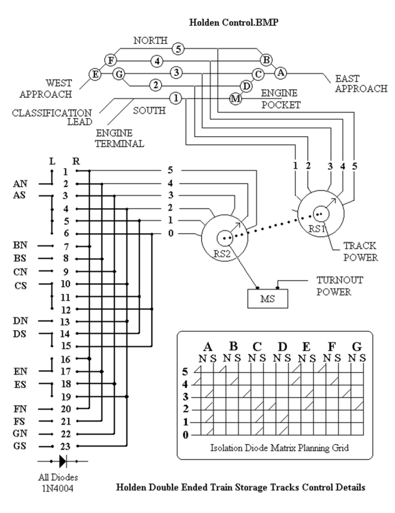
1) trackage, 2) turnout control, 3) track power, 4) electrical planning, 5) construction.
The Yardley & Hillton Railroad has a double-ended yard for storing or staging of trains or cars, it is short but effective and operation is easy. I want to point to the need for a train length approach track to keep a switcher with a cut of cars from fouling the mainline while tending the yard tracks. This is important with a double-ended yard also. Here at Holden only one approach track is long enough, so if I am sorting cars in this yard it must be drilled from one end only, called the Holden Approach track.
If your railroad has an opportunity use a similar route selection method, I hope you find reading the following explanation helpful in understanding the technical details of multiple routes with minimum controls. The schematic representation of the trackage at Holden is at the top of the drawing (file named Holden Control.BMP on page 51). It represents the paths and turnouts involved in accessing those paths. The planning grid shows which turnouts must be in which position for a given route. It is important that we plan this on paper first, and connect the wires last.
Train staging is an option to operation that some feel is very enjoyable. On the drawing, tracks or paths are identified with a number; turnouts are identified with a letter. Freight or passenger trains with locomotives can be stored ready for operation in either eastbound or westbound direction, or the tracks can be used just to store a string of cars.
OPERATION
Minimum element controls keeps operation simple:
Refer to the track plan schematic of Holden Train Storage Yard shown on top of page 51.
Using a rotary switch and push-button to select and power one of 5 routes through this double ended yard makes it about as easy for operation as it can be. The rotary switch selects a route through this double-ended maze and also applies power to one rail of the selected track. The other rail is tied to common for this train throttle supply.
With the trackage as shown at the top of the drawing, we must deal with 5 paths, 4 of which are double ended through tracks. Path 1 leads to the classification yard drill track or engine terminal track. I now think I should have named this track the Yardley Approach track. The 6 position rotary switch is constructed as two separate electrical wipers mechanically connected to move as a unit to any one of 6 positions. That way both track power and turnout route selection is done with a single device. The push button switch MS is the “throw button” to complete the momentary current path to the turnout coils. Rotary switch RS1 controls which track gets throttle power and RS2 selects a path through the diode matrix for turnout route setup. Position #0 serves as a shut off for a loco on track #1. Turnout M is manually thrown and controls access and power to the switcher pocket.
EXPLAINATION OF OPERATION:
On the schematic drawing, RS2 selects the route through the diode maze for turnout control. For example: Route 4, requires that turnout paths AN, BS, FS & EN be set. The planning grid confirms this also. When the throw button MS (momentary switch) is depressed only those 4 turnout coils will move, all others will stay where they were. Locomotive power is applied through RS1. The track is now ready for traffic from either direction. The center terminal of all turnout coils is tied to a common return bus wire below the layout to the return side of the Capacitor Discharge turnout power supply. The supply side of power is tied to the wiper of RS2 through MS button.
PLANNING
The planning grid for this track arrangement is shown in the lower right of the page. You must make your own to suite your own trackage situation. If you have occasion to do these kinds of tricks, probably the most important thing is to get started correctly with the diode matrix planning grid (see the bottom right of the drawing) which prevents the back circuits from interfering with your present selection. Here is where a planning grid on paper helps. It is best understood by visioning train movements as in an east-west direction, and that all turnouts present either a north or south path. One can use this as an educational exhibit for constructing a similar scheme elsewhere. As each turnout has a north or south path, I drew a vertical line for each turnout’s coil identity (a letter) and a horizontal line for each route or path (a number) through the maze. At every junction that needs to be true for a selected route I made a diagonal mark connecting line. These diagonal lines represent the isolation diodes. You need one for each coil/route. They will carry the DC current to move the turnout to the correct path – simultaneously blocking current flow to unwanted coils.
PICTORIAL SCHEMATIC
The rotary switch is shown in the middle and right of the page with the isolation diode tree along the left side of the page. Numbers 1 – 23 represents diodes. The diode symbol is shown at position 24. Polarity is critical. An electrical fact of a diode is that it will carry current in only one direction.
CONSTRUCTION
After getting the tracks laid and mechanically adjusted for proper derailment free running by pulling and pushing a string of cars through all paths of this yard many times at good speed I moved on to electrical controls and planning. Get a sheet of graph paper with a grid of square lines drawn to make the diode matrix planning grid. A 2 pole- 6 position rotary switch is constructed so that the 2 wipers move together to control 2 separate circuits, one is for track power that moves the locomotives and the other is to select the circuitry to move the proper turnout coils.
WIRING
As for construction assembly of the actual diode tree (See photo on the next page) I used two 24 pin solder stud terminal strips mounted beside each other on a board with the diodes soldered across them. I then wired the strip as shown in the drawing on this page. The vertical lines on the diode tree L & R represent connecting wires and are soldered to the terminal studs along with the diodes. For example, turnout coil C-north is wired to diode strip terminal L-9, and coil C-south is wired to L-10, L-11, and L-12. Rotary switch path 4 connects to the strip at R-2 with jumpers to R-8, R-17, and R-21. No terminal stud carries more than 2 wires. All diodes are 1N4004 type 1 amp, 50 volts capacity. The common sides of all turnouts are tied to a return bus wire beneath the Holden yard and then to the capacitor power discharge supply return side. The business side of turnout coils connects to the left side of the diode tree.
For the turnout power return bus I used a 12 gauge bare copper wire strung under the table. This makes for easy soldering. The center taps of all powered turnout coils are tied to this common return line. It connects to one side of the capacitor discharge supply. The other side of this supply is through the rotary switch and the momentary push button. Most connecting wire is 18 gauge twisted pair. I am a firm believer in soldered electrical connections and I solder most rail joints.
The control panel for Holden is built on a small sheet of aluminum that is used for mounting the rotary switch, the momentary push button, a terminal strip between the table and the controls, and a train power selector toggle which controls whether a mainline or the yard throttle runs the trains. The panel is mounted on vertical framing at the edge of the layout table, as there is no other space available. The above description is how to use 2 elements to control power and routing to 5 tracks and 7 turnouts. I like simple minimum element controls. This seems like a relatively few controls for such a flexible operation. But it is all solid state, once it is done, it should give very little trouble, the life expectancy of diodes is considered to be decades.


Leave a comment