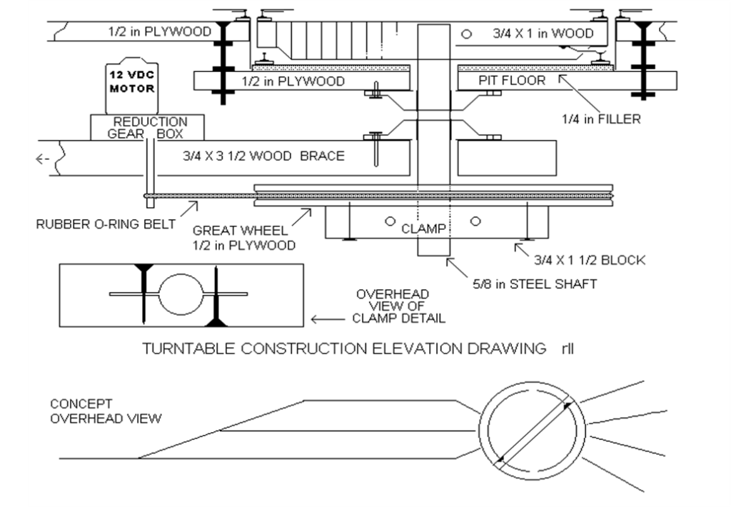
There are several requirements to making a good operating turntable. Among them are a good center support bearing, a good motor gear reduction unit, and a properly mounted and aligned rotatable bridge. This sounds simple enough at first glance, but requires precisions not easily acquired when working primarily with wood as used in model layout construction. I will describe the methods I used to end up with a nicely operating, simply controlled, turntable that can be aligned and held for proper locomotive turning by remote control with ‘no hands on’.
You should take into consideration things like the location of layout framing cross members when placing the table in its final location. It will be larger below the layout than above. The table is supported by a square piece of 1/2 inch plywood a couple inches larger than the diameter of the turntable. This will be supported at its corners by 4 flat head machine screws down through the layout top and through what I call the pit floor. These screws each have 3 nuts, one to lock the screw up against the layout and 2 to adjust and hold the height of this pit floor. It is to this pit floor that we mount our bearing hub and below it will be the large pulley or great wheel for bridge rotation. You could even use this wheel as a handle for manual rotation if you can’t come up with a suitable motor, gear unit.
Find yourself a suitable bearing and spindle arrangement that will allow for mounting the hub to the bottom side of the turntable pit floor, with the shaft protruding through the pit floor not more than the height of the bridge. I used one with a shaft diameter of about 5/8 inch. This I attached to the bottom side of the pit floor. The bearing arrangement should not allow any vertical movement of the bridge assembly.
Referring to the diagram, the brace extends further to the left and is fastened to a layout frame member. It serves a dual purpose. One is to stabilize against rotary movement, the other is to support against the rubber belt tension eventually causing a small amount of movement of critically located components. This way none of the belt tension strain is carried by the pit mounting screws or bridge members. This belt is a rubber “O” ring. They come in a wide variety of lengths, and have no seam or splice to cause roughness in operation. They may be used as oil seals in automatic transmissions. Mine has a cross section diameter of about 1/8″. It seems that you don’t need to tension the belt greatly, just take out the slack. The belt runs smoothly and holds the bridge still for locomotive movements.
We must talk about the motor and gear reduction unit, I wish that I could recommend a source, but I know of none. Mine uses 12 volts DC the same as HO locomotives. It came with a good reduction box attached. I did not use a belt pulley on it, just ran the belt on the knurled shaft with a small length of rubber tubing on the end of the shaft to keep the belt from running off the end of the shaft. This gives lots of speed reduction, which is very important. If I run the table at full throttle it takes about 45 seconds to make a revolution. A good prototypical speed. It can start slowly; reverse easily if necessary to achieve the proper alignment, and stay where you leave it. The next most important element of good speed is the large diameter wheel. It is the hole that was cut out of the layout table. Carefully cutting with a saber saw will produce a wheel that is very round. Then I labored with a handsaw and file in a bench vise to make a groove to carry the “O” ring belt. Thankfully it does not need to be very deep.
When drilling the 5/8″ holes in the bridge and the clamp block be careful that your hole is square and plumb with the vertical reference. Then use the saber saw to cut two slots away from the center hole to give a point of yield for the clamping effect. Fasten this clamp block to the great wheel with a couple screws. I found that I still had some slippage after assembling these pieces to the smooth steel shaft. I was able to prevent unwanted slippage by inserting a piece of sandpaper to bite the shaft when tightening the clamping screws. Use good heavy #8 or #10 flat head wood screws for these. The same was also done with the bridge where the clamping screw heads are concealed by the removable gondola car side panels.
About the bridge; it is about 1/8 inch shorter than the diameter of the pit, and of course must be mounted on top of the shaft at the same height as the layout tabletop. I used the same type of clamping arrangement as with the block on the great wheel. The sides of the bridge are covered with the side panels from some sacrificial Athearn gondola car bodies. This gives the bridge a nice sloped effect at the ends and shows some ribs and rivets, which adds a bit of detail. A couple of the panels near the center are removable for access to the clamping screws if necessary. The bridge is supported only by its center clamp to the shaft. There is no mechanical support of the ends as none is needed with the light weight of our models. This allows for free and easy rotational movement. There is no mechanical track alignment locking device as used sometimes with the prototype, as none seems needed with the rubber “O” ring belt drive. I am a firm believer in fewer moving parts are better.
There are two electrical wipers mounted along the centerline of the underside of each end of the bridge. They are made of brass shim stock and serves to make electrical contact with the split ring rail, which carries locomotive power to the bridge rails. The splits are located 180 degrees apart. Each wiper is wired to a rail on the bridge. They are invisible in operation. I like this electrical arrangement as it provides automatic polarity correction for the engine on the bridge, eliminating the need for a direction switch to the bridge both before and after locomotive turning.
By using a 12-volt DC motor and gear reduction box to power the device we can use the same throttle that powers our layout to be used to control the speed and direction of rotation. By using a double pole double throw switch we control whether the power goes to the layout or table motor. This way there is no need for a switch to turn off the power to the bridge rails. The bridge rails get no power while the table is rotating.
I used paper card stock for the pit wall; perhaps you might cover it with brick paper. This card stock is glued at the top to the edge of the hole in the layout. Let the bottom of the pit wall float, unattached to the filler. On the diagram this filler serves two purposes. 1) It supports the ring rail and its ties, 2) hides the floating lower edge of the pit wall allowing the floor to have some range of vertical adjustment for good alignment with radial tracks. This is done with the bottom 2 nuts on the 4 mounting screws.
To make the ring rail I used a couple lengths of Atlas flex track with the tight ties attached which I diligently bent around a coffee can to get the proper diameter then spiked down to the pit floor filler.
Here are a couple photographs from below the layout table for reference.

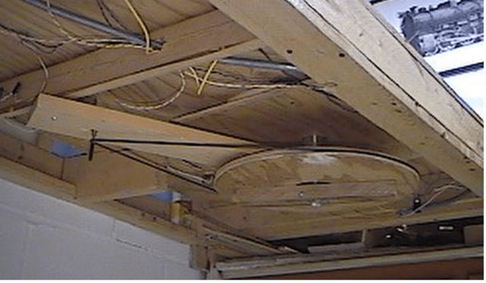
They show: O-ring belt, great wheel and clamp. The brace board with motor and gear box on top is barely visible and the square base plywood board.

Leave a comment