The main line track plan has 3 towns as purported by Lynn Westcott many years ago. Each town has a passing siding and some industries. The theory being that a layout must have at least 3 places for east bound trains to pass westbound ones. Or else everyone always passes at the same place. I thought that trains should be about 8 cars long and that passing sidings must be at least long enough to hold a locomotive with its train. I was careful to make all my passing sidings long enough. However the space between towns turned out to be about the same length. On my layout I found after building and running it that my approaches are bit short for comfort. However, one must live within the confines of the space available to the layout.
After blocking the layout track plan, each town has 4 sections of track, an approach from east and an approach from west and 2 other tracks (mainline and passing track). The tack plan can accommodate 2 operators at the same time on the mainline track. I use DPDT miniature toggle switches to connect any block to either one of 2 throttles. The towns of Hillton and Yardley-Holden each have their own power selection panels exclusive of the mainline.
Below is a representation of a mainline town block and its terminal strip:

Each block of track has a pair of wires soldered to each rail and then connected to a terminal strip under the layout. There is a terminal strip for each town. Now is a good time to name and identify every end of every wire and keep it in a notebook. I think that using terminal strips between the control panel switches and the track elements makes it easier to identify what wire goes to which track device.
Both locomotive power and turnout control are present at the town’s terminal strip. The terminal strip is also a good place for trouble shooting problems though they seldom occur with all the rail joints soldered.
I firmly believe that rail joints should be soldered for good continuity. All the rail joints on the layout were soldered, (unless connected to a turnout). At the time I did this, I was not sure if I would embrace DCC control, so by using the terminal strips between the track and control panel, if I change my mind, all the wiring changes can be done at the terminal strips.
I learned that to solder the rail ends together one must strip away a few cross ties from the ends of the 3-foot lengths of flex track then solder the rails and joiners while the track is laying straight. Curve it around a turn later while nailing it down. Then replace those few cross ties for appearance.
All over the layout for hundreds of trouble free electrical joints I used a good 250 watt electrical soldering gun and 60/40 rosin core solder. Your work has to be clean as new and hot enough to melt solder. A dry iron won’t work; it is the liquid solder that carries the heat. Use smaller irons (25–40 watt) for light work like wires in a locomotive.
Hand Held Transistor Throttle
I have built several of these fine working good feeling tethered transistor throttles.
Here is a diagram of how to build the best Hand Held Throttle that I ever used.
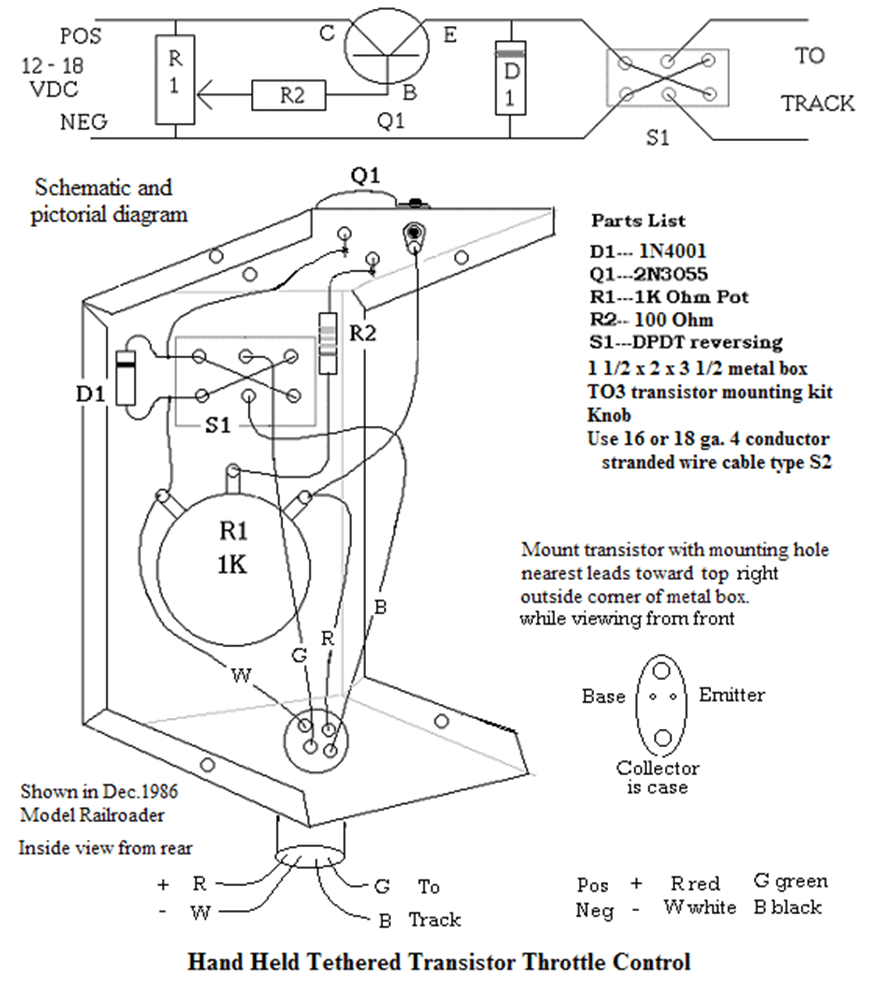
I use hand held throttles exclusively, because I like the way they work. I made my own from an aluminum gadget box from Radio Shack. A nice transistor throttle circuit that uses the popular 2N3055 transistor and how to article was shown in the December-1986 Model Railroader. It sure is handy for assisting the coupling of cars to hold it in hand and walk along with my train as needed. By drilling a hole in the back side and filing it into the shape of a keyhole, I can hang it on a screw head along the edge of the layout where I am working or hold it in hand and walk along with my train. To connect this unit to the layout, I use rubber covered 4 conductor 16 gauge stranded wire which is strong enough to stand on without damage if it gets under foot.
About Capacitor Discharge Turnout Power:
Twin coil turnout solenoids as used in most model railroad turnouts all need relatively high current to get the power and strength required to throw the turnouts. This amount of power with AC is commonly done with about 16 volts at 1 amp or more. If a control button sticks on, a coil can burn out in just a few seconds time. The circuit shown above has enough power to move several turnouts simultaneously and also it automatically safeguards against turnout burnout. It can accommodate additional features for more flexibility in the control of several turnouts.
However a Capacitor Discharge circuit uses a relatively weak transformer to charge a large capacitor through a rectifying diode and a current limiting resistor. This charging process takes a long time perhaps 2-5 seconds. During this time the weak transformer, through the resistor, is just not strong enough to damage a turnout. If a short were to occur, as with a stuck control button, it would simply swamp the supply harmlessly, and not smoke a turnout coil.*
One of the characteristics of capacitor discharge is to hit hard for a brief time. As capacitors only store DC voltage, this charge through the half wave rectifier can build to over 25 volts. That is enough power to move several turnouts at the same time. This amount of power applied to 6 -10 turnout coils only lasts for less than a tenth of a second, which is not long enough to burn out a coil. I used a small 16 VAC half amp transformer and an 11000 microfarad 30 volt capacitor (about the size of a can of soup) to power all the turnouts on the layout. The transformer is small but the capacitor is large. This controlled power is applied only to small sections of the layout at a time through local micro-switch. (Mainline or Hillton or Yardley or Holden) *I have had a few Peco turnout closure rails break at the throw bar. — Solder a wire thru small hole in the bar.

Using diodes to provide for additional control features beyond conventional turnout power.
Using DC voltage to move turnouts allows some extra control features not available with AC voltage as is common with conventional power packs. One of these features is the ability to control several turnouts with a single multiple position rotary switch and an isolation diode matrix to stop the back circuit in multiple turnout arrangements. (see page 48 on Holden Staging control) Another feature is the ability to control a given turnout from two different controlling positions (as at Hillton control page 71). The main characteristic of a diode is to pass current in one direction only. We can use them to power the turnout coils that we want and at the same time block the back circuit to those paths that we don’t want. It is almost like magic.
When 2 different operators need to use the same trackage, (as on my layout at Hillton) four turnouts may need control from 2 different panels (inside and outside the center pit). Using isolation diodes and DC voltage prevents the other man’s unattended panel from canceling your turnout choice. This gives us the ability to control a given set of turnouts from either outside or inside the operation pit. When I operate alone, it is sometimes necessary, for coupling chores, to duck under and use the other panel, abandoning the one I started with. All works well with this arrangement.
I like using walk around tethered throttles, and if I can reach a turnout, I throw it by hand, this saves money, and only if it is out of arms reach do I power it electrically. The main line has 9 powered turnouts, the town of Hillton has 6 and Holden has 7 electrically powered turnouts. The classification yard with 15 turnouts required a larger supply (bigger capacitor) for dependable operation. Each of these locations is an operable section with a push button micro-switch through which all the turnouts in that section are thrown or re-thrown at the same time. I use readily available, miniature single pole double throw toggle switches for each turnout (that way the handle position can indicate the position of the turnout points) but no power flows until the throw button, a single throw momentary contact switch, is depressed. At the top of this page is the schematic drawing of the circuit I used for this turnout power supply. I use a mix of Atlas, Peco and other twin coil turnout machines.
For a power supply I use old toy train transformers and silicone diode bridge rectifiers to acquire the 14 -16 volts DC to feed to the transistor throttle. My layout uses 4 of these homemade throttles. Old Lionel or similar 100-watt transformer work quite well for HO scale trains. There is a small 16 volt transformer for capacitor discharge voltage to power turnout movement. These power supplies can be built and tucked away out of sight in an obscure corner of the layout.
Hiding Power supplies out of site:
I located the transformer-rectifier power supplies in an out-of-the-way corner of the table under the scenery and posted the outputs on a terminal strip under the layout. The layout has 5 supplies. A & B are for the mainline, C for Hillton and D for Yardley-Holden. There is a small supply for turn-out power. All the wires of a town are connected to a terminal strip for that town under the table. I used over 600 feet of 18 gauge twisted pair plastic insulated wire for the entire layout job. The 12 pair cables between the overhead mainline block selection panel and the layout is in addition to this. There is also a couple terminal strips terminating the cable wires inside the overhead block control panel.
The operational capacity of the layout is compact and well balanced. For example the yard holds enough cars to replace the ones on both interchange tracks or to exchange all the cars at both the mainline and Hillton industries. The engine facilities have capacity to house the engines and cabooses to power the trains to those 3 or 4 destinations. The double ended staging yard can hold 3 complete trains to or from Hillton or the mainline along with an escape track if desired.

Leave a comment