Good ideas in control panels – Overhead block-throttle selection.
Here are some of my ideas and methods for conventional train controls. This is about how I dealt with the two train control system as advocated by Linn Westcott and others.
After building a model train layout so big that it was jammed against 3 walls of my 11 x 13 ft. basement train room, one comes to the realization that there is just no room on the table for a control panel. So why not mount it on the ceiling? That is just what I did by fastening four 2×2 legs from the overhead floor joist and then screwing a piece of plywood to these 4 legs. Like an upside-down table. It extends down approx. 2 feet from the ceiling. Then I used 2 hinges to mount the wood frame of the control panel box to this inverted platform. Such an arrangement allows easy drop down access to the inside of the panel and keeps dust off which keeps it nice and clean inside. I had some multiple conductor plastic covered electrical cable (12 pair – 18-gauge) to use between the panel and the train layout. This is heavy enough to carry one ampere without much line-loss. I ran four of these cables to the underside of the layout table. I should have run five.
My overhead panel measures 14x18x3.5 inches and provides space for the mainline block throttle selection and turnout control toggles. The mainline uses 2 of these tethered throttles, A and B. Either throttle can operate any block of the mainline. There are a couple other throttles at the busy towns of Hillton and Yardley.
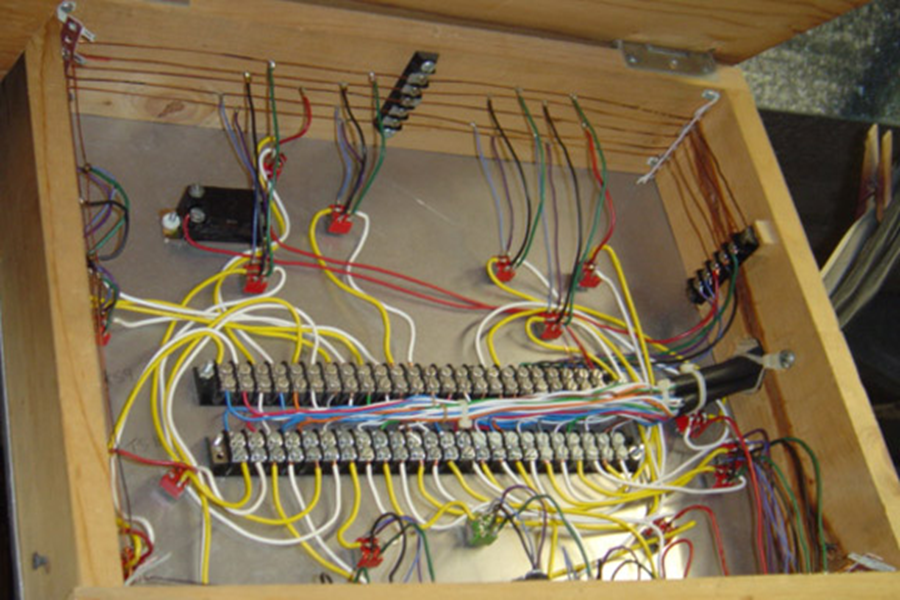
If we are not careful, the inside of a control panel can become a jumble of wires that can be nearly impossible to work in if you have to change out a bad switch. I recommend a terminal strip inside the control panel to help separate the wires to the layout from the wires to the control switches. I used two 24 contact screw type terminal strips (from scrap electrical gear) inside this overhead control box. A terminal strip is also called for under the layout at the other end of each of these multi-wire cables, one for each town or location around the layout. There I used solder type 12 pin fiber-board stripes; an example can be seen in the photo on the bottom of page 19. Now this gives an opportunity to make notes as to which wire goes where for later identification. With terminal strips one can make a listing of every end of every wire and keep these few sheets in a notebook for future reference. In years of use the wires to the layout may never give trouble unless snagged and broken accidentally while poking around under the layout, but the control switches may wear out occasionally. Trouble shooting a problem can be done at the well labeled terminal strip.
Also an idea that helps keep the area inside the panel workable is to physically locate the most numerous common wires toward the outside allowing the center area to be used for the detail connections and space for your hands while working in there. This allows for separation of input supply wiring to the panel and output wiring from the panel to the table. I built my panel from a box made with 1×4 lumber and an aluminum sheet on which to mount the control switches. Aluminum is nice to work, as it is soft and easily drilled for mounting toggle switches. Around the inside walls of this box, I made a 5 wire buss of 12 gauge bare copper wire supported with 4 small terminal strips at the inside corners to carry the common wires consisting of power from A and B throttles and turnout supply power through a heavy duty micro-switch. The common return for this turnout supply is a bare 12-gauge wire under the layout running near all the turnouts. I acquired lots of DPDT miniature toggle switches from obsolete electronic gear. I did mass production of soldering 6 pigtail wires to each of these 12 block control toggles and 3 wires to the 7 turnout controls at the work bench vise before mounting them to the supply buss and terminal strip inside the panel box.
About using a cookie sheet for a control panel:
Sheet aluminum makes a nice material for a control panel. It is not too thick like Masonite so electrical switches mount well, it is easy to drill holes for mounting toggle switches and it even looks good if left unpainted. The rolled edge of a 1-inch deep “Baker’s Sheet Pan” from a kitchen utensil supply store can provide both strength and good looks, is smooth to touch and doesn’t need paint. By using miniature toggle switches with soldered connections one can save a lot of space.
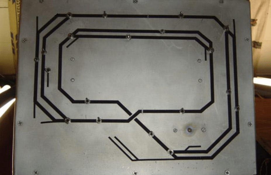
One should devote some time to the planning of the track diagram on the face of our control panel. You must consider both inner and outer size requirements when designing the track diagram. First I made an actual sized grid paper pattern to get an accurately sized pencil drawing of the track plan. Upon this paper drawing I could lay the physical components to get an idea of their size and spacing requirements arranged before assembly. Be aware that these components take more room inside the panel box than outside where we work them. One must give consideration to the physical size of the toggle switches as well as a nice feel to the locations for operation of these switches.
For decoration, I used black self-adhesive stripping tape from the automobile parts store, paint department to make a simple schematic representation of the mainline track plan attached directly to the aluminum. I used a sharp Xacto knife to trim the tape. Take your time and work carefully here, as you want this to be neat looking. I located turnout controlling toggle switches at junctions of these lines and block control toggle switches in strategic locations within a block line. After applying the black tape in the proper pattern, I drilled holes in the proper places for switches and buttons. Be careful here that the drill bit doesn’t snag the tape and tear it loose. Then I took it outside in the good air and sprayed a couple coats of clear varnish on the whole thing before mounting the switches. This serves to help protect the stripping from peeling off. It has held fast for several years.
This aluminum sheet over a wood frame has worked well as the main line control panel. At other locations around the layout I made smaller “local” panels. They are handy for mounting turnout and throttle choice toggle switches and buttons at Hillton. I was able to get 2 small panels by cutting them with a hack saw from one baking pan that originally measured about 12 x 9 x 1 inches. These small panels are mounted vertically on the edge of this crowded layout that has little room left for control panels.

Leave a comment