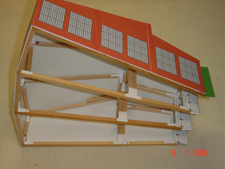
After deciding that I could use a compressed space roundhouse, because none the proper size were commercially available, I came to the realization that I would have to scratch build my own. This began a period of over 15 years of procrastination. During which time I had acquired a large sheet of 1/16 thick white plastic that I believed would make good material for the sides and roof, which could be covered with brick paper for appearance. I got a bundle of ¼ inch square wood sticks cut by my friend with a table saw. I eventually drew a quick sketch of a plan, which I felt would be the proper proportion of the structure. Then I drew a full size plan for this frame on a large sheet of ¼ inch square grid paper for a pattern or template for the frame members. I thought that a frame element between each stall would be proper. A three-stall roundhouse would need four of these frame assemblies. Each frame would consist of 8 different sized pieces. With this template I could measure and cut the various size pieces for each bent.
So I cut the ¼ inch square sticks of pine to proper length for the frame members. Within the trestle business those frame members are called ‘bents’, I am not sure if that term applies here. I used waxed paper laid over the actual size drawing to keep from gluing my frame members to the template. I soon learned that waxed paper moves very easily over the plan drawing. However I persevered, keeping a watchful eye on the movement of my template papers. I wanted to use waxed paper so that if a bit of glue seeped out under the framing sticks it would not ruin my drawing. Realizing that butt joints are not very strong, I applied a gusset of card stock paper about an inch square over both sides of each joint, hoping this would make it all stronger.
After building the 4 bents I pondered what would I do to tie these stall frames together so that they could support a roof and end walls? Perhaps I could add cross members by supporting them with card stock gusset angles. I used temporary blocking and internal bracing (which was later removed) to hold things in place during assembly of the frames. As I was building this over existing stall tracks fastened to plywood tabletop there was no way to hold the frame bottoms in proper position. I later learned that some roundhouse kits use a floor to hold the vertical framing in place. I could not do this with my stall tracks already nailed down and wired in place.
I had a skeleton of framework assembled. To make the sides I traced around a bent onto my sheet of plastic, cut the two to size with straight edge and utility knife, and then secured them to the outer frames with Walther’s Goo. I held them down with weights overnight.
The longer I worked at building this thing the more I found wrong with the original framing. Something was wrong, but why was all this so poorly sized? It seemed that it would be stronger if the roof were attached. I turned it upside down on the sheet plastic and traced the outline, cut it out as one piece from the 1/16-inch thick sheet plastic with a utility knife and straight edge. Then trim fitted it to size, discovering that nothing is square on a roundhouse. As I attempted to attach the roof I was surprised to find that it seemed like it was going to have a hump in the middle. Back again to my original poorly sized frame elements. I had a couple frames in the middle that were too tall. The more time I spend with this the more I feel that I should buy a plastic kit. However those all seemed too big for my cramped location so near the big bridge for Hillton overhead. And I might have to relocate some stall tracks slightly. I guess that I should have been more careful about getting the butt angles more accurate. As this is the first chance to get frame members the wrong size. I used white glue for all the joints in the frame and gussets. This stuff needs almost an overnight to dry hard.
I puzzled a few days as to how to salvage my mess. I had 4 frames of 2 different sizes. I was nearly ready to trash the whole thing. My problem was caused by my own carelessness. Originally I had carefully cut 4 of each stick to proper length because there were 4 bents. A couple sticks were only 1/8 of an inch different in length. However, during assembly I got them mixed up and did not notice it till the glue was dry. This accounted for the different height bents. This is partly due to the fact that I did not secure my waxed paper to the drawing template. Shame on me. I was becoming discouraged and disgusted.
There were some discrepancies in fit but I kept going. An accomplished scratch builder, Dean Freytag, offered me encouragement by saying that I should not be too critical too soon, that it all will work out in the end. I took his advice and stayed with it. I decided that I could still buy a plastic kit if all failed, and that I could make the decision to trash it all at a later time, so I stuck with it and applied the plastic sheets for sides, ends and roofs to the frame bents with Walther’s Goo which did a lot to stiffen it all up. The longer I worked with this the better it all looked.
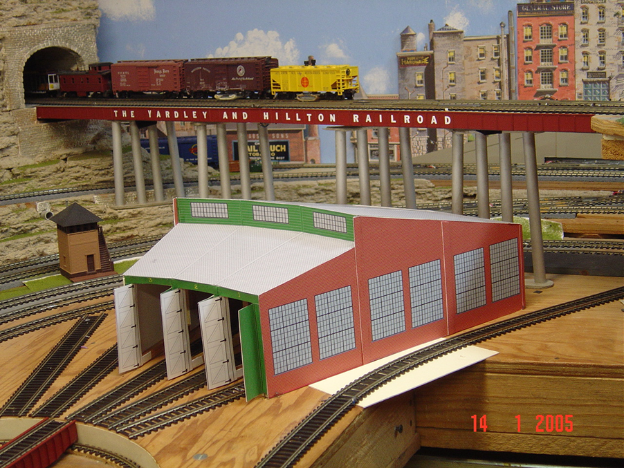
Then the most rewarding part of the whole thing was using the computer and MS Paint program to make transparent drawings of brick mortar joints, which I applied over a brick-red colored rectangle. I drew opaque windows to overlay on those same bricks. I made back wall end panels using the same windows. I made printed light gray shingle roof covering. Because the side was too large to print on a single sheet, I decided to make my side with printed windows just large enough to cover 1/3 of the structure and paste 3 of these identical sheets on a side and cover the seam between with a pilaster, also of the same brick pattern. These I printed on heavy card stock (110# paper) with a conventional color ink home printer. Be careful in the future not to get it wet as the ink is not waterproof. I used rubber cement (white glue won’t hold) to secure these prints to the plastic panels covering the frames after trimming the prints to final size with scissors.
The roof was covered the same way only using a different size grid pattern, printing it wide enough to cover the largest point of the pie shaped section of roof and covering the seam with a narrow strip of shingles similar to the ridge cap on homes. The longer I worked with this the more enjoyable it became. Making a drawing of sides and ends with large industrial type windows (opaque) with the computer was enjoyable and rewarding.
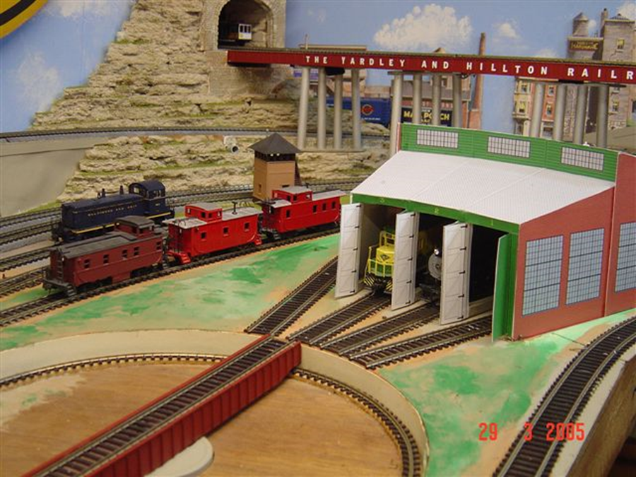
It was challenging to make the printed doors, which would be glued in always open position, to the exposed frame members, effectively hiding them, the doors would have a different image whether inside or outside surface. I decided on green painted “V” groove siding for the outside and white diagonal braced for the inside. I drew them with the computer using my imagination as to how such a tall narrow door should be braced. I also made the header over the door ways with the stall number printed on it. After I finished putting it all together I realized that my door openings were a bit too narrow to clear the NMRA standards gauge, this is undoubtedly due to my cramped space. It will however clear all my locomotives, so I am happy.
All totaled I spent nearly 100 hours with this project, but after muddling through my early troubles, it all seems worth it. The financial cost is practically nothing considering that the plastic was left from an earlier and unrelated job. I found some suitable ventilator stacks at the hobby shop and filed an angle on their bottoms to fit the roof slope and mounted them with Goo.
Soon I felt moved to assemble and paint the plastic kits for coal dock and water tower that had been in their boxes for so many years. I wanted a car repair building. I had a small plastic kit building that covered a single track. But things were just too crowded; the building is now in Hillton. I gained space by eliminating one outdoor stall track and re-aligning the caboose track slightly, using a small side building for caboose supplies. The next thing was painted grass and gravel to cover the plywood.

Leave a comment