About using duplicate toggle switches for controlling some turnouts:
To save money, I throw most of these turnouts by hand. The town of Hillton on my layout is too wide to reach across for throwing all the turnouts by hand. Here at Hillton I used Peco turnouts exclusively, because they work well. Still it is nice to be able to turn a steam locomotive around on the ‘Y’ track so it can run forward for the return trip over the branch line. A convenient way to do this is to power critical turnouts for remote operation. I have two control panels for operating these critical turnouts one on the outside of the layout and another inside the pit for convenience of operation. That way I can control all the necessary turnouts whether I am inside or outside the operating pit. I have duplicate control switches for some of the turnouts. This requires the use of DC voltage for power and isolation diodes to prevent the other toggle switch for a given turnout from canceling your selection. The electrical tricks I describe here may be applicable to other layouts also.
The operation of Capacitor Discharge powered turnouts requires 2 steps. First step is to set any and all toggles for route selection. Nothing happens till the second step, which is to depress the MS button, which actually causes things to move. For operation you throw the toggles required for this move of the locomotive and follow with a depression of the MS momentary push button which makes final contact and all of the turnouts controlled by this panel instantly move to this new position whether they need too or not. Regardless if they were previously moved by hand or by the other panel, they will move to this new setting. The second operator may be surprised if you throw a turnout under his cars!
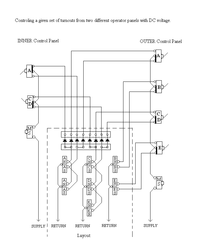
To help your understanding, I refer you to two drawings, the pictorial electric schematic drawing called ‘Hillton Turnout Control’ (page 71) and the layout trackage drawing called ‘Hillton Electrical Blocks3’ (page72). On the track plan drawing note that the 2 turnouts labeled ‘A’, comprise the bridge crossover and are wired together in parallel and move as a unit as well as the 2 labeled ‘C’ & ‘D’ enabling access to the ‘Y’ connector track. They are wired to move together because one would never need to go into that connecting track without being able to get out at the other end. That fact also prompts us to use a relay to control the polarity of the tail track ‘T’. This works where the tail track is short and not used by other throttles or routes, thus the required polarity reversal can be automated for easier operation. Atlas makes a relay that is ideal for this because it uses the same kind of power that we have on the layout and it “remembers” the last move without using any other power. By tying the coils of this relay parallel to the connector track turnouts we can have automatic polarity control of the tail track. The contact side of the relay is wired as a DPDT reversing switch and used to reverse the polarity of the tail track when turnout ‘D’ is against travel to or from the left. Normally all the tracks on the table, including the tail track, follow the direction polarity of one throttle, when access to the connector track is enabled, the relay reverses the tail track direction automatically.
Using a relay for automatic polarity of ‘Y’ turning tracks
Note on the control panel pictorial (Hillton Turnout Control) that one toggle switch from each panel controls both turnouts labeled “A” on the track plan and also that one toggle of each panel controls both turnouts “C & D”. Shown also is the relay “K” that follows the “Y” connector turnouts (“C & D”) It provides for automatic reversal of a locomotive on the connecting track using the ‘Y’ track to turn the locomotive around.
Referring to the track plan drawing, the operation of turnouts B & E are simple. But A, C & D require dual control and that requires diodes to isolate against the back circuit of two control points. I only powered the turnouts that I could not reach by hand from both the outside and inside the operation pit of the table. For identification on this diagram, the turnouts are labeled A B C D & E. While operating inside the pit one can reach turnouts B & E easily, so they are thrown manually while there. Turnouts A, C & D require duplicate toggles for control from two different panels.

I have attempted to add a bit of color to the track diagram, ‘Hillton Electrical Blocks3’ for easier understanding of connections to the relay. On this drawing, blue denotes track power; green indicates Capacitor Discharge power for turnout movement; and red is for insulators. Only the contact connections to the relay are shown. The coil connections are parallel to turnouts ‘C’ & ‘D’ shown on the other drawing. Showing colors may not work with some printers but it is nice on the screen. The fact that the town can be split for operation with 2 different throttles is not shown on this drawing.
The required wiring connections for turnout routing are shown on page 71, in the drawing ‘Hillton Turnout Control’. The center of the drawing shows the isolation diodes, which is the real meat of this project of duplicate turnout controls. Along the right side of the drawing is the control panel for the outside of the layout and the inner panel is shown along the left side of the page. Only 2 turnout routes need duplicate controls, remember I am cheap, if I can reach it, I throw it by hand. See photo on this page of a turnout control panel.
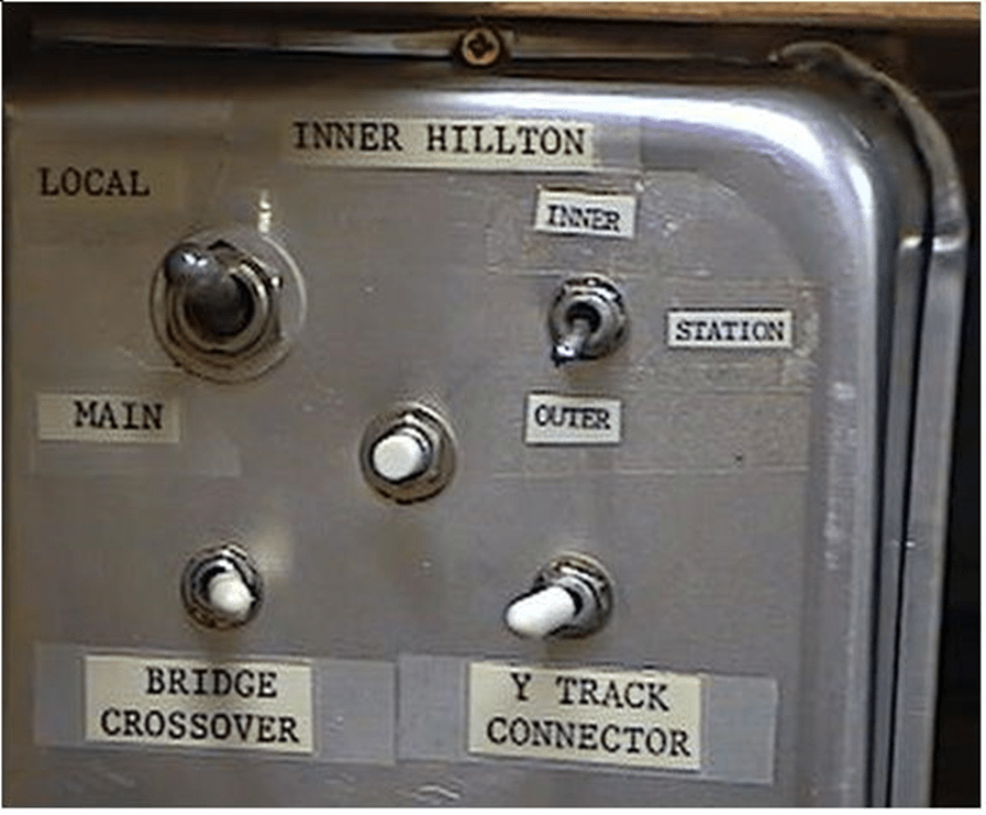
The uses for the switches on this panel are as follows. The large center off toggle at the top left is for throttle selection, either the local Hillton throttle or Main line A or B. The A or B is determined by which is powering the Hillton Junction branch access siding. This is how the town can be split between 2 operators. The small toggle at top right (DPDT) is for which throttle powers the section of track in front of the Hillton station. The bottom two toggles with white handles are to control turnouts (A & C D) movement through the push button in the center, a momentary contact micro switch.

Leave a comment