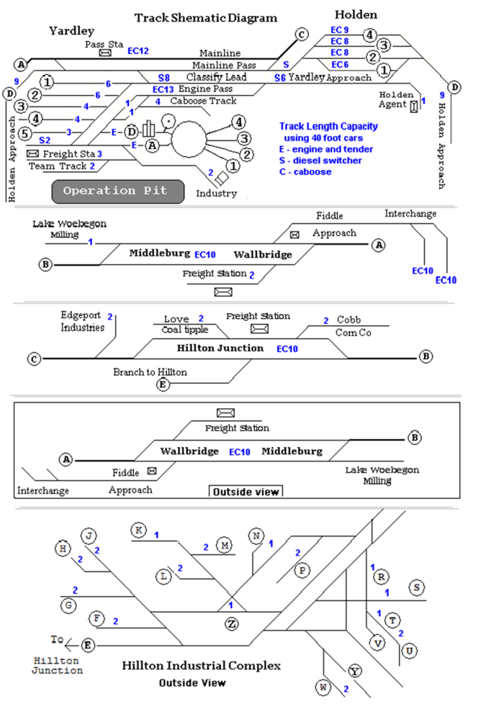
Yardley and Hillton Railroad Track Schematic Diagrams Explained
This sheet helps explain the Track Schematic Diagrams of each town as shown on the previous page. It is intended to support and add detail to the overall track plan. By using this straight-line scheme it makes labeling with a typewriter easier. Most curves are not shown. Track turnouts and curves are shown as 45 degree angles. Tracks crossing at grade level are shown as 90 degree angles. This drawing method causes lots of distortion when including the “Y” at Hillton. The blue printing is for understanding track car capacity.
At the top of the page is the Yardley classification yard along with the Holden staging yard. One must realize that this drawing completely encircles the 2 x 6 foot operation pit. The track labeled Holden Approach (9 car capacity) is actually one piece of track, 9 cars long between turnouts. There is an alternate view of this trackage on page 66.
The next two items down the sheet are for the main line towns of Middleburg and Hillton Junction. The circled letters A, B, C, D, and E are continuation flags. For example, if a train leaves an interchange or fiddle track at Wallbridge and Middleburg via flag B it will arrive (after passing over simple track) at Hillton Junction flag B. (trains run from A to B to C to A.)
These drawings are shown as viewed from inside the operation pit with the exception of Hillton and the [boxed view] of Middleburg. Most of Hillton can be operated from either inside or outside the pit. The lower end of Middleburg (freight station) and Wallbridge (interchange tracks) are worked from the outside but the upper end (Lake Woebegone Milling) from inside the pit preferably with a helper brakeman for best operation. Another explanation begins on page 72.
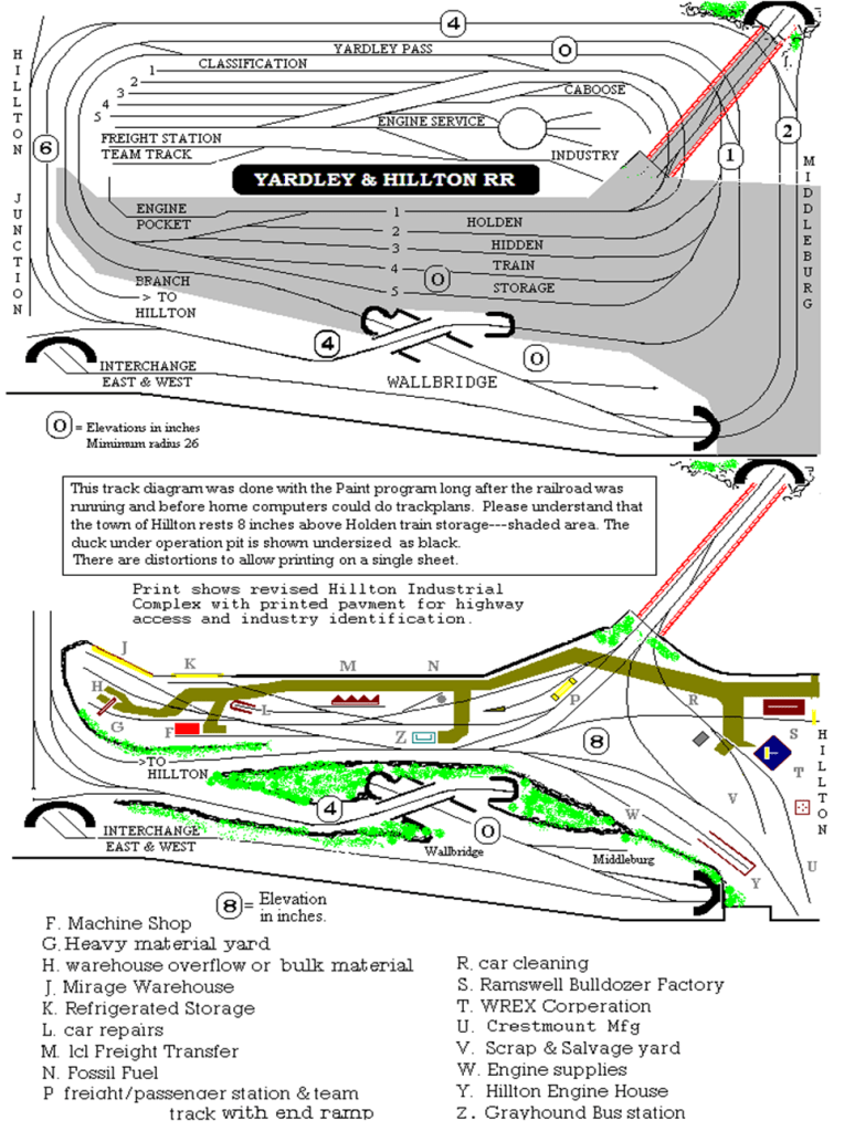
The remaining letter bubbles are to identify industries and their locations at Hillton:
F. Machine Shop (uses gondolas, flats and occasional box car)
G. Machine Shop Heavy Materials Yard (gondolas & flats, has overhead crane)
H. Warehouse overflow track and bulk material conveyor (hoppers or boxcars).
J. Mirage Warehouse Track (doors for 2 cars at one time usually box cars).
K. Modern Refrigerated Storage (gets refrigerator cars from interchange).
L. Car Repair Shop (light rail car repairs).
M. Slims Freight Transfer (transfer between rail car and highway trucks).
N. Old Fossil Fuel Co. (coal and oil).
P. Hillton Freight and Passenger Station (usually box cars or flats the at end ramp).
R. Car Cleaning Spot (works on call from the tailgate of a pick-up truck).
S. Ramswell Bulldozer Co. (heavy materials or flat cars).
T. WREX Experimental cars or special cabooses.
U. Crest Mount Mfg. Compact Camper Trailers..
V. RR Scrap & Salvage Co. (gondolas or flats)
W. Engine supplies & fuel track.
Y. Engine house.
Z. Greyhound Bus Station.
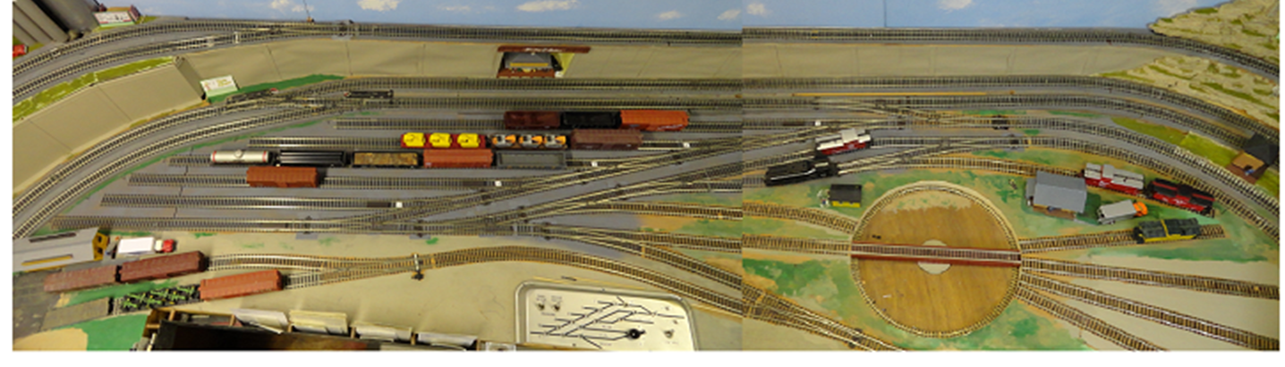
This is a view with coal dock, water tank and roundhouse removed to better show the track arrangement. This is two photos tacked together near the middle. I wish I had better software for that. The overall span is about 10 feet. The black switcher near the turn table pit is using the short runaround track to get to the other end of a caboose.
We can see everything that Yardley offers but the train length runaround and the Underhill Fabricating business lost in the lower right corner. (Turn the photo 90 degrees right) The classification drill track and engine pass track combine to make a 13 car runaround connecting to the yard approach track. (Holden #1 track)
From the extreme right is the Yard Master’s Tower, 4 roundhouse radial spur tracks, caboose track and its building, turn table pit, engine hostler’s office, crossover connection between mainline pass and yard drill track. The 5 stub ended classification tracks of 25 car capacity, the passenger station tucked into a hole in the concrete inclining lap of mainline, both turntable approach tracks, the control panel, switchback access to the freight station and separate team track with end ramp, and pockets for car cards.
This easy to operate (while seated on a stool) Classification Yard – Roundhouse Engine facility accomplishes all the chores needed in a rather small space. It has two runaround tracks, both a car long and a train long. This yard can hold 3 trains worth of cars, cabooses and locomotives.
Yet the Yardley operator can service Holden Freight Agent and the train staging yard at his back on the other side of the pit.
The next page starts construction notes and diagrams of the communities served on this room sized layout.
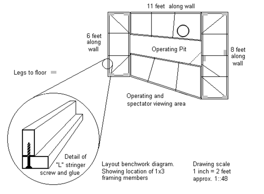
Construction notes about the layout bench work and carpentry:
Refer to the diagram on the next page that shows an overhead view of the framework. This duck under layout clears the floor by 39 inches. As I get older I find that using an old office chair with casters makes ducking under easier.
The bench work was made from 1×3 inch furring strips (actual dimensions 3/4 x 2 1/2) as sometimes used behind paneling on a concrete block wall. I used two of these fastened together with screws and glue in an “L’ shape. (Enlarged detail view on next page) This is similar to “L girder construction” but upside down. The bottom of the L supports the 1×3 cross members which can be located anywhere as needed to support the track support vertical members. This seemed strong enough initially but after 20 years it developed a bit of sag.
I made two table frames; one measures 24 inches wide by 72 inches long with 4 1×3 legs extending to the floor support it; it rests against the left wall of the room. The other table is 30×96 inches, standing on 4 1×3 legs and against the right wall. The space between these tables was filled with two legless bridges of 1×3 frame supported with steel splice plates screwed to the bottom of the left and right tables. I used a brace to the floor at the center of the right table. A helpful trick I learned during construction was to use a temporary leg (2×2) to the floor, which I could move to directly below where I was working to support the weight of hammering and screwing while laying track. It takes the bounce out of the table and makes driving nails easier.
The inner bridge-tables are irregular shaped to fit as required and to give the best compromise of space to both the table and the operation pit. The rear table is 24 & 32 x 77 inches and located against the back wall. The front table measures 26 & 37 x 77 inches. This gives as much room to Holden and Hillton as possible and still leaves a just barely adequate pit space of 21 & 28 x 77 inches. I weigh 160 pounds, if I was a bit heavier, that space would be too small. I did not want to fasten the tables to the basement block walls for future cosmetic reasons. The layout table that I have is firm with no shake.
I used 1/2 ” plywood for track sub base board. I used the cookie cutter method of cutting the plywood with a saber saw. Be sure to allow enough width past the track centerline for roadbed. This is supported about every 14 – 18 inches to the table frame cross members. I used “C” clamps to hold the support verticals at the proper height while gluing and setting screws. I used a splice board about a foot long glued and screwed below butt joints in this sub base. I marked the track centerline with straight edge and pencil. For the curves I used a yard stick with holes drilled every ½ inch for a nail to act as radius center. The other end had a notch to guide the pencil while drawing curved track centerlines. The cork roadbed center was then laid to this mark.
Before nailing the roadbed down I spray-painted it all light gray. I did this en-mass one day by temporarily laying the cork strips on a scrap piece of plywood. I worked out of doors for good air circulation to avoid fumes and sprayed them all with automotive primer paint “bomb” as some would call it. If you do this make sure to separate and turn the strips to properly color the slopped edges of the cork roadbed before painting. I think it looks nearly as good as ballasted track and is a lot easier and quicker. I dislike ballasted because of the noise transfer to the table. My track work is code 100 Atlas flex track, has served well and is cheap.
Most of the tabletop is large pieces (less than a full sheet) of 1/2-inch plywood. There are 4 of them, one for each of the communities of Yardley, Holden and Hillton. The one for Hillton Junction/Holden City actually is cut in two along the curving track line of Hillton Junction and the outer half is mounted on vertical supports about 6 inches higher than the inner half. These were nailed directly to the frame cross members.
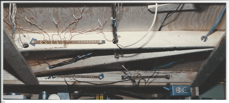
I drilled 3/4″ holes through some cross members to pass wire though and mount terminal strips. It is not good to have hanging wires below the duck under table. I mounted power supply transformers out of sight in corners under the scenery.
After nailing down the roadbed and track to the plywood sub roadbed I glued stacked layers of broken ceiling tile for the rock like strata along the cut of the RR right of way. When breaking the ceiling tile ‘rock cliffs’, clamping between a couple boards helps to get a long straight edge.
The ‘concrete retaining wall’ incline is covered with heavy card paper and electrical tape pilasters painted gray to hide the vertical roadbed supports. A section of this around the inside of a curve is assembled from small strips of cardboard glued together then painted. It is removable to retrieve a derailment. (See page 21).
Construction Notes and Photo
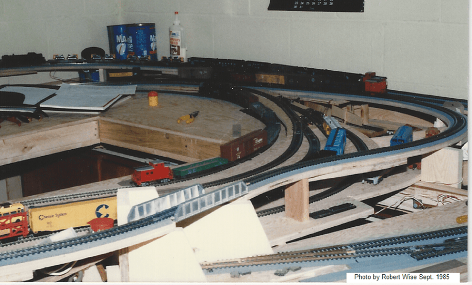
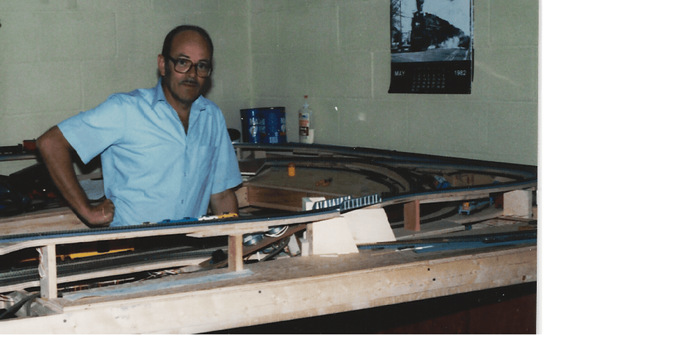
While I was readying this work for the printer, I discovered a few pictures taken in September 1986 during construction that I had forgotten about. So I scanned them for inclusion here. They were taken by my friend about a year after construction on this layout had started. It shows some interesting points that have been out of sight for so many years after the addition of the upper deck of Hillton.
It shows mainline trackage on risers that is now hidden inside tunnels. It looks like the classification yard drill track/engine facalities track were not yet finalized. I remember running trains forward and backward on the Holden staging tracks for hours of testing. The blue coffee cans in the corner are where the Hillton big bridge terminates in the Wherezatgo tunnel.
Notice the note tablet for wiring terminal identification laying where the roundhouse-turntable became. The aluminum colored rivited plate bridge at Wallbridge in the foreground has been changed to a more interesting truss type. The classification yard was not yet laid or the town of Hillton, they came probably a year or two later.

Leave a comment